Nearly 2 years in development with and for today’s warfighters. A complete re-thinking of a comms suite – not only how it looks but how it works! No confusing chipped cable assemblies that have to be periodically programmed/updated. The 21GC™ comms suite simply works out of the box – the way a comms system should work. One-time vest setup / completely intuitive while avoiding conflict with other vest-mounted operational equipment. Patent-pending.
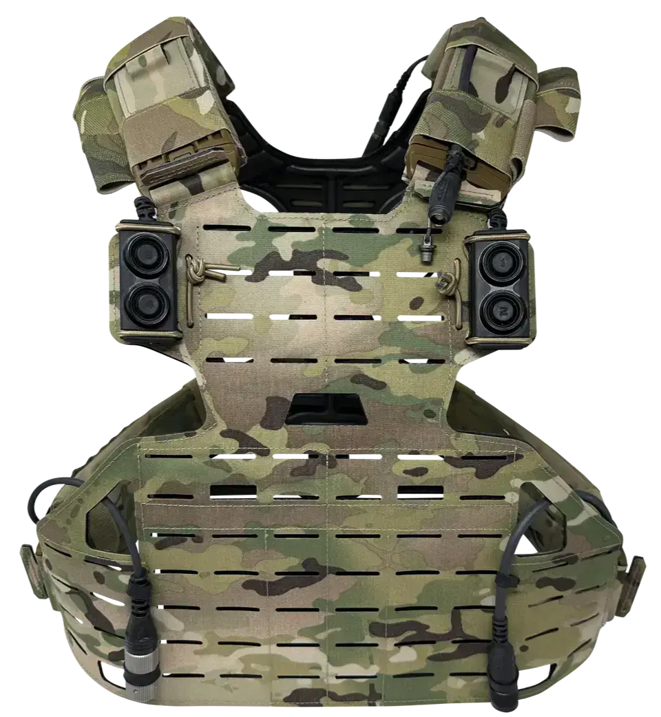
The 21GC™ (aka 21st century game changer) communications suite was designed to redefine and relocate the “vest real estate requirements” of traditional push-to-talks to the user’s back; all the while maintaining ease of access to an old-school, traditional-style, push-to-talk’s functions on the front of the vest. The 21GC™’s form factor affords the operator the space needed for an EUD (end user device) mounted on the chest while still providing ample space for up to four (4) PTT switches (as shown). The 21GC™ was designed over nearly a 2-year period with a specific, influential, U.S. special operations client. It was designed to be used with dual net and traditional military radios, commercial portables (law enforcement) as well as ground, air, and waterborne intercoms. The system features localized connections for quick radio, headset, and intercom cable swap-outs, depending upon mission requirements, without having to undo and re-weave various cables throughout the vest’s molle system. The 21GC™ emphasizes seamless integration into a set of all-new distinctive traits and characteristics designed solely for tactical implementation. The picture to the right depicts the traditional 21GC™ setup for multiple radio use with two 1″ x 2.5″ x .75″ PTT paddles – one located at each side of an EUD case (a single paddle option is also available now and is upgradeable to a dual paddle kit in the future). Radio cable assemblies shown at the bottom (6 pin 152 left / 19 pin 163 right) feature quick disconnects located at the operator’s sides for ease of access and rapid radio cable swap-out.
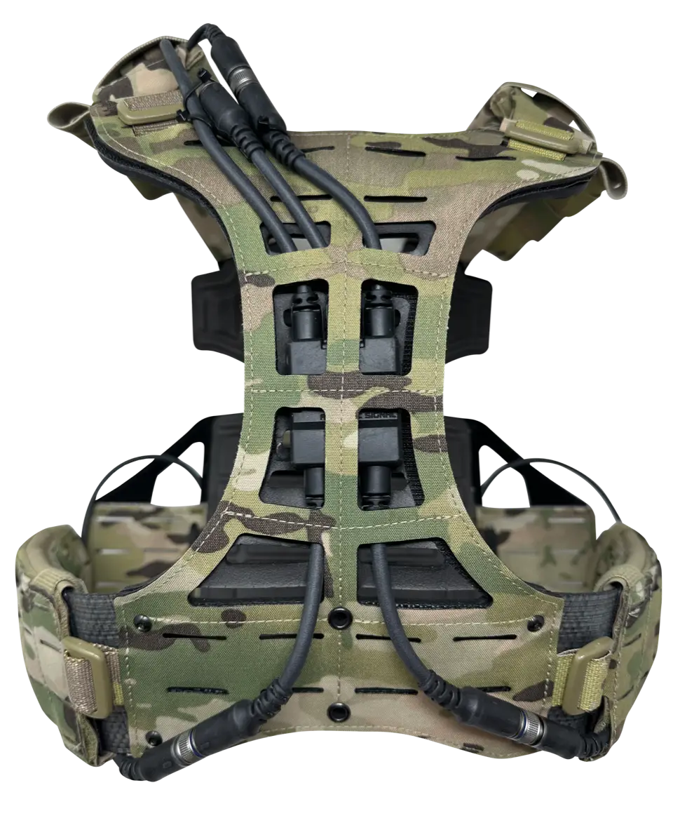
The “core” (aka the circuitry brains of the 21GC™) was designed to be worn on the rear/backside of an operator’s vest. The vest shown here was designed by S&S Precision in Virginia Beach. In this instance, the ‘holder’ in the rear of the vest is obviously perfect for housing the 21GC™ — allowing the three cable leads at the top (headset connection / ICS connection / PTT paddle(s)) and the two lead cables exiting the bottom of the core housing (radio cables) to either be weaved through molle straps or through a conventional shoulder pouch for the top flying cable leads, as shown. You can see, in pictures below, how the core can easily be mounted and left ‘permanently’ on a more standard molle vest. The ‘core’ measures a mere 1.5″ wide x 2″ tall x .25″ thick and holds the sealed circuitry inside. Using a molding method and machine originally designed for Tesla, we are able to 100% seal the core – eliminating concerns associated with dust, dirt, and water ingress. The core and its cable assemblies all meet 20 meters for 2 hours submersion expectations/requirements for maritime operations. By eliminating a conventional dual comm/dual net push-to-talk from the front of the vest, we’ve opened up crucial space required for an EUD or other critical piece(s) of kit. As an aside – we continue to receive calls and emails from clients being shown 21GC™ “knock-off” concepts for consideration. First off – there are pending design and utility patents for the system we will vehemently defend in court, and secondly – be cautious of what you’re trying to copy – there is considerably more going on inside the core housing than one might think – inside the housing is much more than the circuitry found inside a traditional push-to-talk box/housing.
The 21GC™ paddle housing incorporates the same design and manufacturing philosophy as the rest of the comms suite — while ruggedized and easy to use — it’s as small as it can be without making it difficult to access and depress. The paddle system shown at the right is a single system providing two PTT buttons, partially shrouded, with a tactile feel when depressed and released. The PTT housing with switches can easily be zip-tied in place by the operator – removing the potential conflicting size of an alligator clip or molle clip bracket from the rear of the switch housing. The single PTT paddle can operate both channels of a dual net radio or a single channel of a dual net radio (the other channel being used for data) and a single net radio (i.e. PRC-152), or it can be used with two single net radios and so on. The connector on the opposite end of the paddle features a stainless steel connector housing with a screw-on sleeve — this prevents the paddle (or any other like cable assemblies of the 21GC™) from inadvertently becoming disconnected. Furthermore, the screw-down sleeve acts as a highly protective shield/barrier, between the male and female connectors, from potentially harmful dust, dirt, and water ingress. As previously mentioned, the 21GC™ paddle assemblies are available in a single paddle style, as shown in the picture to the right, as well as a dual paddle version as shown in photos above and below — providing double the connection and use capabilities as the single paddle version.
Side view of the low-profile push-to-talk dual paddle system of the 21GC™ communications suite. All the flying cable leads exiting the top of the back-mounted “core” housing feature stainless steel, over-molded, multi-pin, female connectors which, after being weaved through a single traditional vest sleeve, end purposely at the position of laying across the top of the vest shoulder terminated with a stainless steel debris prevention cap. It is here, at this point, that the male cable assemblies can be mated with their female counterparts and screwed down tightly to avoid accidental disconnection. The male cable assembly options include a connection for multiple styles of headsets/earpieces, another for ICS cable assemblies as well as the connection point for the single or dual paddle push-to-talks.
Side view of the low-profile push-to-talk dual paddle system of the 21GC™ communications suite. All the flying cable leads exiting the top of the back-mounted “core” housing feature stainless steel, over-molded, multi-pin, female connectors which, after being weaved through a single traditional vest sleeve, end purposely at the position of laying across the top of the vest shoulder terminated with a stainless steel debris prevention cap. It is here, at this point, that the male cable assemblies can be mated with their female counterparts and screwed down tightly to avoid accidental disconnection. The male cable assembly options include a connection for multiple styles of headsets/earpieces, another for ICS cable assemblies as well as the connection point for the single or dual paddle push-to-talks.
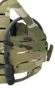
Closeup of the 21GC™ “core” &
how the flying cable leads exit the top and bottom edges of the “core” and are captured in MOLLE strips.
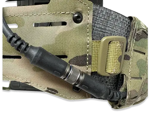
Right, front view of a 21GC™ 19-pin / PRC-163 cabled radio connector. As described previously, all radio cable assemblies for the 21GC™ are designed to provide the end-user the capability of quick swap-out. Rather than traditional 18″, 24″ or 36″ long cable assemblies that connect directly to a PTT housing worn somewhere on the vest, the 21GC™ radio cable assemblies feature the standard 21GC™ inline screw-on/unscrew stainless steel disconnect. Each disconnect is positioned approximately 6 inches from the actual radio connection—strategically aligning with the side of the vest’s cummerbund, providing quick, easy access for an end-user to unscrew/disconnect his cabled radio connector and swap out to another. No need to unweave buried cables from a MOLLE vest’s front/back side, unplugging from a PTT box/housing and beginning the process all over again to install a different radio interface cable.
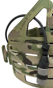
Left, front view of a 21GC™ 6-pin cabled radio connector. As described previously, all radio cable assemblies for the 21GC™ are designed to provide the end-user the capability of quick swap-out. Rather than traditional 18″, 24″ or 36″ long cable assemblies that connect directly to a PTT housing worn somewhere on the vest, the 21GC™ radio cable assemblies feature the standard 21GC™ inline screw-on/unscrew stainless steel disconnect. Each disconnect is positioned approximately 6 inches from the actual radio connection—strategically aligning with the side of the vest’s cummerbund, providing quick, easy access for an end-user to unscrew/disconnect his cabled radio connector and swap out to another. No need to unweave buried cables from a MOLLE vest’s front/back side, unplugging from a PTT box/housing and beginning the process all over again to install a different radio interface cable.
Closeup of the 21GC™’s stainless steel connectors. The male and female connectors line up and are pressed to engage each other. Once interlocked, the male outer sleeve is designed to screw down onto the female, preventing accidental disconnection as well as protecting the connector assembly pins from the negative impacts associated with dust, dirt, and water exposure.
Close-up of the 21GC™ “Core”—also known as “the brains” of the 21GC™ communications suite. As stated previously, the “Core” measures an insignificant 1.5″ wide x 2″ tall x 0.25″ thick, yet it is double overmolded to prevent any form of debris, including dust, dirt, or water, from entering the unit. Exiting the top of the “Core” are three double overmolded stress/strain reliefs for the three 21GC™ connection cables, designed to be worn over the shoulder of the vest. These connection cables include: